
Continuous upflow filtration
Solids are retained within the moving single-grade sand bed.
FILTRATION
Upflow deep-bed filtration with an airlift and integral sand washer for water, wastewater polishing and reuse.
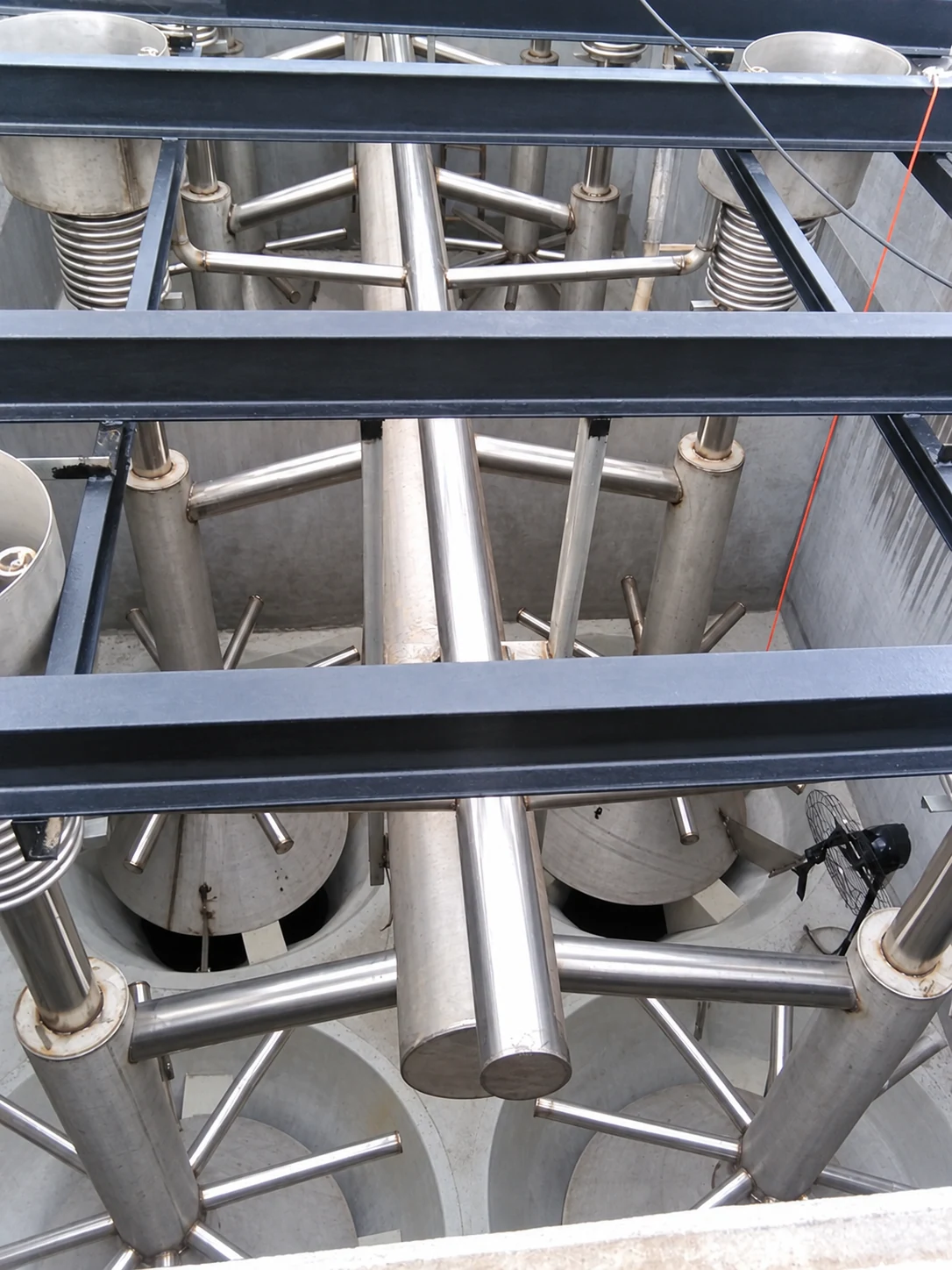
TECHNOLOGY & CONFIGURATION
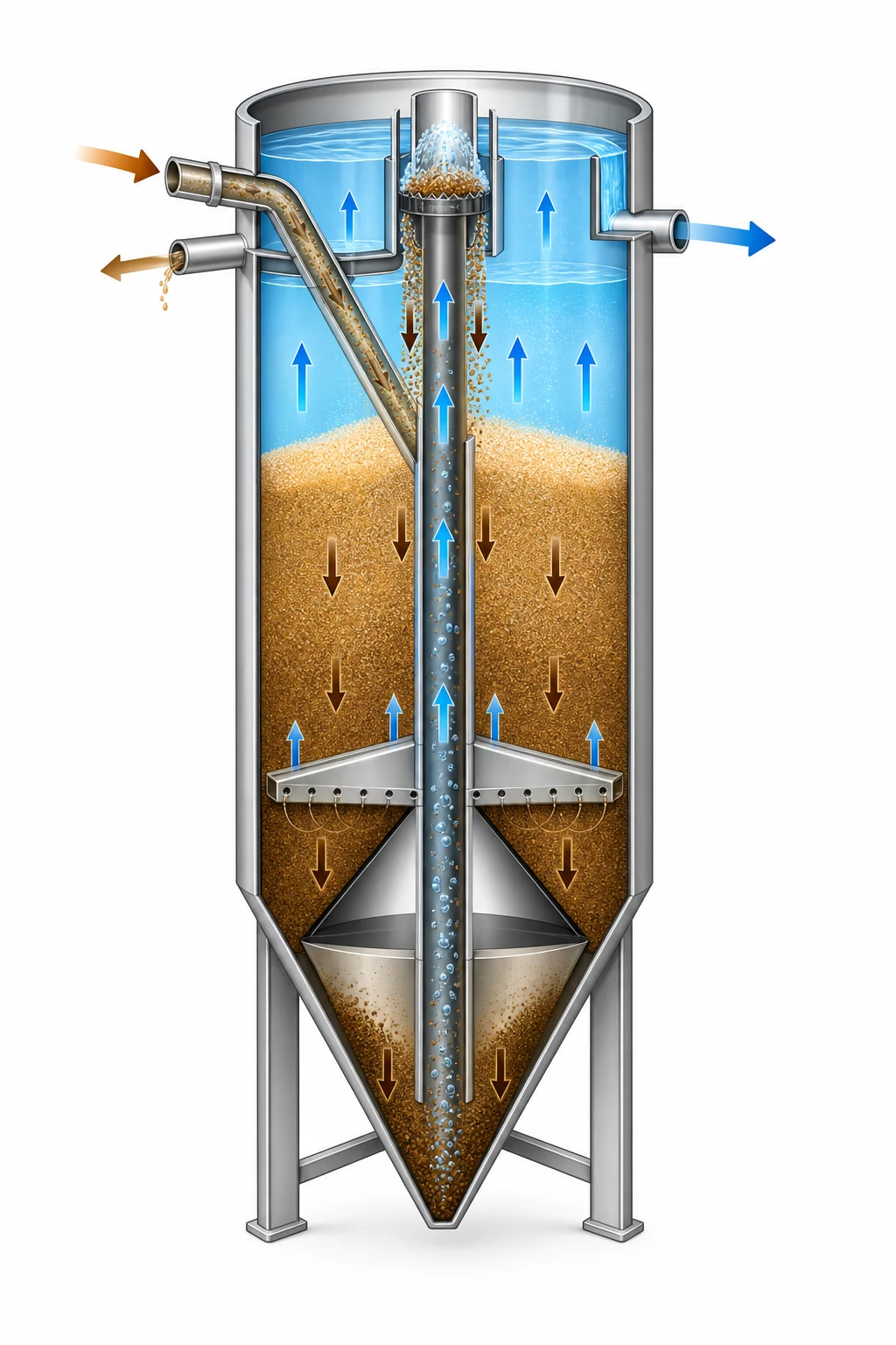
Water rises through a descending sand bed. The airlift transfers dirty sand to the washer; cleaned media returns to the bed while washwater carries away the separated solids.
Solids are retained within the moving single-grade sand bed.
Compressed air lifts sand to the washer without a submerged mechanical drive.
WORKING PRINCIPLE
Illustrative cutaway. Blue arrows indicate water or airlift movement; brown arrows show the sand movement and waste stream.
PRELIMINARY SELECTION
Published ranges support initial selection. Final equipment, dimensions, materials and performance commitments follow the confirmed project requirements.
| Model | Filter area | Capacity, m³/h |
|---|---|---|
| CSF-15 | 1.5 m² | 9–18 |
| CSF-30 | 3 m² | 18–36 |
| CSF-40 | 4 m² | 24–48 |
| CSF-50 | 5 m² | 30–60 |
| CSF-60 | 6 m² | 36–72 |
| CSF-70 | 7 m² | 42–84 |
Ranges are indicative and are not universal performance guarantees. Additional sizes and arrangements are available on request. See the product datasheet for the detailed selection basis.
PROCESS & SUPPLY BOUNDARY
Supply inclusions and options are confirmed in the agreed quotation. Installation, commissioning and operation are available in Jordan, Iraq and the UAE; installation supervision and commissioning are available in other countries.
REQUEST A QUOTE
COMMON QUESTIONS
The filter washes media continuously while filtering. It does not need a separate high-rate backwash pump or dedicated backwash sequencing; normal isolation valves remain.
The datasheet lists filter media and initial charge among the extra options. It should be explicitly included in the agreed offer where required.